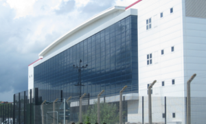
About the Datacentre in Newport South Wales
The data centre campus in Newport South Wales is one of the largest in both the UK and Europe, currently offering some 70MW of constructed capacity and rapidly expanding to over 200MW across the original building and two new adjacent plots.
Originally opened in 2009 the datacentre was acquired and expanded in 2020 with most of the capacity being taken up by hyperscale operators, however there are dedicated halls for “smaller clients” seeking use of the facility.
Within the UK this is one of only two wholesale focussed campuses away from London and the M25, so offers diversity at scale, as well as servicing the needs of the smaller local market from south Wales or the Bristol/south-west England region.
The new data centre facility which is located to the southeast of the existing data centre was recently given the go ahead by the local authority area of Newport City Council to be constructed.
To guarantee constant power supply to the data centre, even in the event of a catastrophic power outage, the site power backup is supported by 60 standby diesel generator sets (Kohler type KD1650, 3MWth,).
These gensets operate on a very short-term basis during the year, typically for testing purposes only, or in the very rare event of a loss of power.
However, the operator was required to obtain an industrial permit from Natural Resources Wales, due to the total thermal capacity of the proposed standby generators exceeding the Part A (1) criterion of 50 MWth of the Medium Combustion Plant Directive (MCPD) that stipulates a maximum NOx limit of 190mg/Nm3@15%O2 for the generators.
Newport City Council in its “Air Quality Supplementary Planning Guidance (2018)” suggest that the principal pollutants associated with combustion engine emissions (standby generators, vehicles, construction plant) are oxides of nitrogen, which forms nitrogen dioxide in the atmosphere.
Therefore, this meant that the engines needed to be retrofitted with SCR (Selective Catalytic Reduction) which was supplied by IMS (Industrial and Marine silencers) to reduce NOx levels by up to -90/95%.
About the Generators
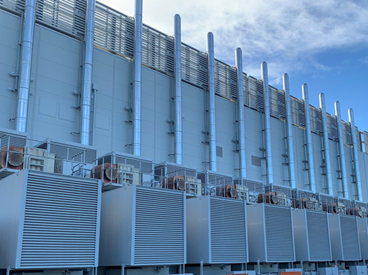
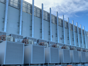
The 60 x Kohler KD1650 Gensets are fitted with KD45V20 (45Ltr/1200kw) Engines which are all housed within an acoustic enclosure with Air Inlet/Air Extract Attenuators (as shown below) and the roof mounted SCR system and twin silencers from IMS that not only reduces NOx levels far below the allowable MCPD Limit of 190mg/NM3@15%O2 but also reduces noise levels below 65DB(A)@1m.
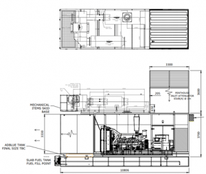
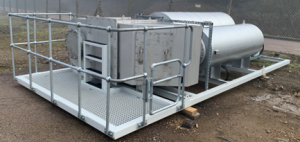
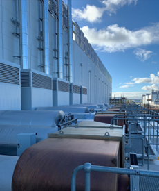
The photograph below shows the IMS Primary Silencer followed by the SCR System and our secondary silencer all mounted on a skid with safety rails and swing gate for roof access along with our Electronic Control Panel with a prewired loom that feeds all sensors/injectors on the SCR system. That means once lowered into position on the roof of each enclosure all that was required to be done was to connect the power to our cabinets along with a CanBus Signal and the adblue tank sited above the Slab Fuel Tank and commissioning could commence.
The SCR Reactor is designed with a removable lid and access hatch for access to the catalyst substrates if they ever needed to be inspected or maintained.
About the SCR System
The IMSeco SCR System is a “Closed Loop” controlled Dosing and Monitoring Package with NOx, Temperature and Back Pressure Sensors, Airless Injectors and an ECU housed within a Control Panel that not only guarantees to meet the MCPD Emission Levels but because of its configurable AdBlue Dosing Strategy can be set to provide the most economical adblue consumption.
How the SCR System Works
The SCR system comprises of the following components:
- SCR+ASC Catalysts
- MAP Sensor (Air Intake Pressure) or CanBus Signal
- Exhaust Temperature Sensor
- NOx sensors (Engine Out and Tailpipe)
- ECU
- AdBlue Pump – RPU
- AdBlue Injector
- Backpressure Sensor
- AdBlue Buffer Tank
- Speed Sensor (RPM) or CanBus Signal
SCR/ASC Catalysts
The SCR System injects a measured amount of the AdBlue Solution (32.5% Urea in Water) under pressure which is hydrolysed to produce an ammonia gas that is required for the NOx (NO/NO2) reduction across the SCR catalysts. There needs to be enough SCR catalysts to provide enough surface area and catalyst volume to be able to obtain the NOx conversions required on each engine.
In the unlikely event that too, much ammonia is produced in the dosing process, IMS always uses a bed of ASC (Ammonia Slip Catalysts) after the SCR Catalysts to prevent any excess ammonia gas from exiting the tailpipe.
NOx Sensors
The “Closed Loop” system utilizes two NOx sensors that measure “Engine out” and “Tailpipe NOx” which gets stored within the ECU for downloading to provide “Real-Time” NOx reduction reporting of emissions reductions.
Data Logging
The following parameters are logged in the SCR systems ECU (note this is not an extensive list, more parameters can be monitored) and can be visually checked on the Digital Display on the front of the Control Panel
- Date/Time/Work Time
- Exhaust Gas Temperatures
- Air Intake Pressure/Air Intake Temp
- AdBlue Level/AdBlue Injection Pressure/AdBlue Consumption
- Injection Status – On or Off and Pump Status – On or Off
- Injection Time On/Injection Time Off
- NOx – Engine Out/Tailpipe
- Airflow In/Airflow Out (Exhaust)
- Any Error Codes
As well as the parameters listed above the ECU also records pressure drop, RPM, turbo pressure and engine operation time with exhaust gas flowrate.
If errors occur the ECU records them, all of which are date/time stamped so that they can be downloaded later and reviewed/updated for maintenance or warranty purposes.
AdBlue Dosing System/Tanks
The system is supplied with a Bunded AdBlue Tank which is fitted with a KUS Type Level Sensor (Pump and In-line Filter) that draws the AdBlue from within the tank and delivers it to a pressure rail where it gets pressurized for injection into the exhaust. The amount of adblue that is dosed is determined by the exhaust flowrate and other information obtained from the engines CanBus System by the ECU along with the NOx Levels and Exhaust Temperatures that the ECU obtains from the pre/post NOx Sensors and Temperature Sensors so only the correct amount of AdBlue is consumed to provide the amount of NOx reduction required. The ECU will self-adjust the dose rates depending on the parameters measured.
The Level Sensors within the tanks measure the Adblue levels and provide several warnings should the adblue levels get low. If the AdBlue is not replenished water will be recirculated from a closed loop water system with small tank to prevent the Injectors from overheating.
Installation and Commissioning
As most of the installation was conducted within the IMS Facility in Shepshed, Leicestershire, the final install and commissioning on site only took around two working days per set to complete.
For commissioning to take place the engines had to have been commissioned and shown to be running stable and that there were sufficient levels of Adblue/Urea within the Tanks before we could begin to undertake the initial checks of the systems including electrics, instruments, and pipe connections to ensure that they were all functioning correctly and that there were no exhaust leakages within the system.
On completion of the commissioning a report was generated to demonstrate MCPD compliance. In this case rather than just meeting the 190mg/m3@15%O2 NOx limits set by the MCPD Directive, we reduced the Raw NOx from 1729mg/Nm3@15%O2 to 85mg/Nm3@15%O2 which is a NOx reduction of approximately -95%, less than half of the MCPD allowable limit of 190mg/Nm3@15%O2.

For more information on our IMS-eco SCR Systems visit www.silencers.co.uk