Project Details
- SCR Technology for University of Bristol
- United Kingdom
About University Hospital Bristol:
University Hospitals Bristol is one of the largest NHS Trust Hospitals in the Southwest of England with a combined workforce of over 13,000 staff. The Trust delivers over 100 different clinical services serving a core population of more than 500,000 people. The hospital offers services from the neonatal intensive care unit to care of the elderly with diagnostic, medical and surgical services including cardiac and cancer services.
In October 2019 the Hospital Trust declared a climate emergency and together with Bristol City Council announced their ambitious targets to go for carbon neutrality by 2030.
A major issue for the University Hospital in achieving carbon neutrality by 2030 was the fact that they were almost entirely reliant on large steam boilers for its site heating and hot water demands. So early 2020, the Trust embarked on the first phase of its vision to de-steam the Bristol estate with the installation of a heat network to supply the hospital buildings using a combined heat and power system (CHP) as a mechanism to fund the works. As part of the works, they also decided to upgrade the “Standby Power” capability within the hospital adding an additional power plant room and installing SCR on all of the five generating sets that powered the hospital in an emergency.
About the Generators:
The University Hospital Bristol has 5 off “Standby Generators” all Cummins QSK60 G4 60 Ltr Displacement Engines all operating at 2250kva/1760kw, 50Hz, 1500rpm which needed to be upgraded with SCR Emissions Reduction Technology to comply with MCPD (Medium Combustion Plant Directive) requirements to meet NOx Levels of no more than 190mg/Nm3@15%O2 to be allowed to continue to operate.
Engine Type: | Cummins QSK60-G4 (4-cycle, T/C, A/C) |
Fuel Type: | Diesel Powered (EN590) |
Configuration: | V16 Engine |
Capacity: | 60.2 Ltr |
Bore and Stroke: | 159mm x 190mm. |
Rated Speed: | 1500rpm |
Power Rating: | 1636KW (Prime) 1760K (Standby) |
Electrical Rating: | 2045kVA (Prime) 2250KVA (Standby) |
Fuel Consumption: | 437 1/h (Standby) 100% load |
AdBlue Consumption: 271/h (Standby) 100% Load |
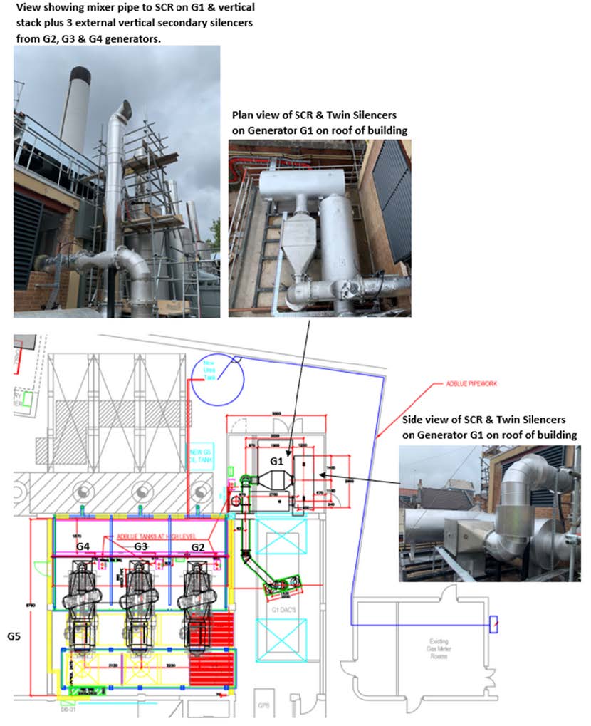
Requirement for Generator G1 housed within a plantroom the exhaust runs vertically to the roof of the plantroom and then through the plantroom wall where the exhaust pipework on the external face of the building bends through 90deg to the existing silencers before extending vertically approx. 3.5 metres to its termination point.
IMS decided the best position for the SCR Reactor and replacement silencers would be externally on the roof of the control room adjacent to the plantroom as shown below:

Requirement for Generators G2, G3 and G4
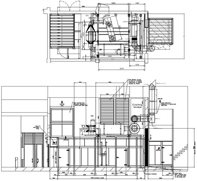
The next 3 generators were all positioned in a common plantroom adjacent to each other with a mezzanine floor above the open engines and twin vertical “Primary Silencers” up the one side of the plantroom. IMS Decided that it would be best to position the mixer pipe for the SCR Reactor at high-level using a “2-1” manifold and siting the SCR Reactors also in a vertical position on the opposite wall with the exhaust pipework running down towards floor level before turning 180 degrees into the secondary vertical silencers positioned on the external face of the building as shown below:
General Arrangement Drawings showing Twin Vertical Silencers, Mixer, SCR, and external secondary silencer Generators 2, 3 and 4:

Work began on upgrading the exhaust systems with the IMSeco SCR Systems on Generators 1-4 in June of 2020 where each set was upgraded individually as the other 3 had to remain operational in case of an Electrical Outage as power would be required by the Hospital in an emergency.
At the same time as the SCR System were being installed a new plantroom was being prepared for the additional fifth Generating Set (again a Cummins QSK60-G4 Open Set in the adjacent building.
IMS prepared all of the structural work by creating a mezzanine above where the new engine was to be installed while at the same time installed a large 10,000 Ltr AdBlue Bulk Tank external to the plantrooms with transfer lines from a Remote Fill Cabinet to the Bulk Tank as the nearest point that a tanker could get to the compound was some 30 metres away.
Requirement for Generator G5:
Once the new engine was in place for generator G5 within the new adjacent plantroom, IMS began on the installation of the Mixer, SCR Reactor (sat horizontally above the engine) along with a new primary and secondary silencers with exhaust ductwork that ran 3.5M vertically external to the building as shown below:
General Arrangement Drawings showing SCR & Twin Silencers for new Generator Building Gen5
Designs for Cummins KTA38 and KTA50 Generators (Tittesworth, Leek and Monkmoor):
The total program was conducted over several months in a number of phases between June 2020 and November 2020 with the commissioning of the sets being completed before year end.
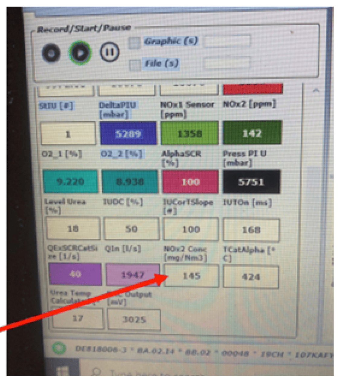
Using our OBD (On-Board Diagnostics) Software we were able to demonstrate Compliance for the MCPD (Medium Combustion Plant Directive) on all 5 engines with a NOx reduction of around -90% as can be seen in the screenshot below.
An environmental permit was issued by the Environmental Agency allowing the engines to be operated.
At full load the “Engine-Out” NOx (NOx 1) measurement was 1358ppm which was reduced to 142 ppm (NOx2) measurement at Tailpipe (145mg/Nm3@15%02) a NOx reduction of almost -90%, 24% below the allowable 190mg/Nm3@15%02 by MCPD.
The AdBlue Dosing could have been set higher to obtain even better reductions, but it would have only increased the adblue
System on full load @ 1500rpm.
NOx2 reading 145mg/Nm^3
Site Plan showing positions of all 5 generators along with the proposed position of a large 10,000 Ltr AdBlue Bulk Tank fed from a remote fill cabinet which is the nearest point at which a tanker can get access for filling the AdBlue Bulk Tank.
About the SCR System:
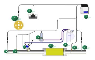
How the SCR System Works:
The SCR system comprises of the following components:
- SCR+ASC Catalysts
- MAP Sensor (Air Intake Pressure) or CanBus!
- Exhaust Temperature Sensor
- NOx sensors (Engine Out and Tailpipe)
- ECU
- AdBlue Pump – RPU
- AdBlue Injector
- Backpressure Sensor
- AdBlue Buffer Tank
- Speed Sensor (RPM) or CanBus Signal
SCR/ASC Catalysts:
NOx Sensors:
Data Logging:
- Date/Time/Work Time
- Exhaust Gas Temperatures
- Air Intake Pressure / Air Intake Temp
- AdBlue Level/AdBlue Injection Pressure / Ad Blue Consumption
- Injection Status – On or Off and Pump Status – On or Off
- Injection Time On/Injection Time Off
- NOx – Engine Out/Tailpipe
- Airflow In/Airflow Out (Exhaust)
- Any Error Codes